First block of an approach to integrating existing eurorack modules into a simple HD video synthesis system.
http://mediumrecords.com/vs0/vs010/vs010.html
presented at Seeing Sound Symposium 2020
First block of an approach to integrating existing eurorack modules into a simple HD video synthesis system.
http://mediumrecords.com/vs0/vs010/vs010.html
presented at Seeing Sound Symposium 2020
this has been rather ready for quite some time now. engineering department requested time for various revisions related to general stability; happy to say they’re pleased with the latest figures and the gang down at art and language can pick up where they left off. Big thanks to the people at TARO for moral support. AV evidence coming soon.
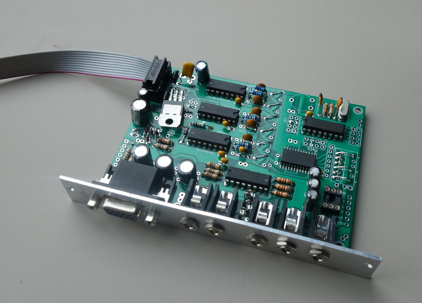
exploded view
no signal – out of sync – blue-screen-of-death, etc. etc.
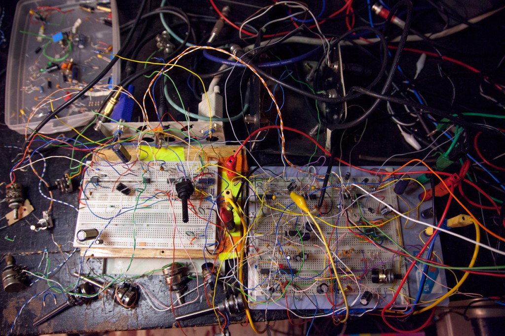
…circuit-bending, running video through audio-gear, home-made electronics experiments…
A number of approaches to video experimentation can tend to corrupt the signal’s synchronization information. Although a lot of older CRT television monitors don’t seem to mind so much, and will even produce some rather nice glitches, newer monitors and video projectors can be particularly picky. Recording directly to tape or other video capture devices is most often out of the question without a good stable sync.
One common workaround is the use of a TBC (time base corrector) or video mixer (preferably with an integrated TBC). This usually works, but as a solution it can be either not-so-portable, expensive, an aesthetic compromise, all of the above, or some combination there of. In my case, the video mixer i have is quite low-rez and I loose all the nice analogue gradients I’ve been into producing lately.
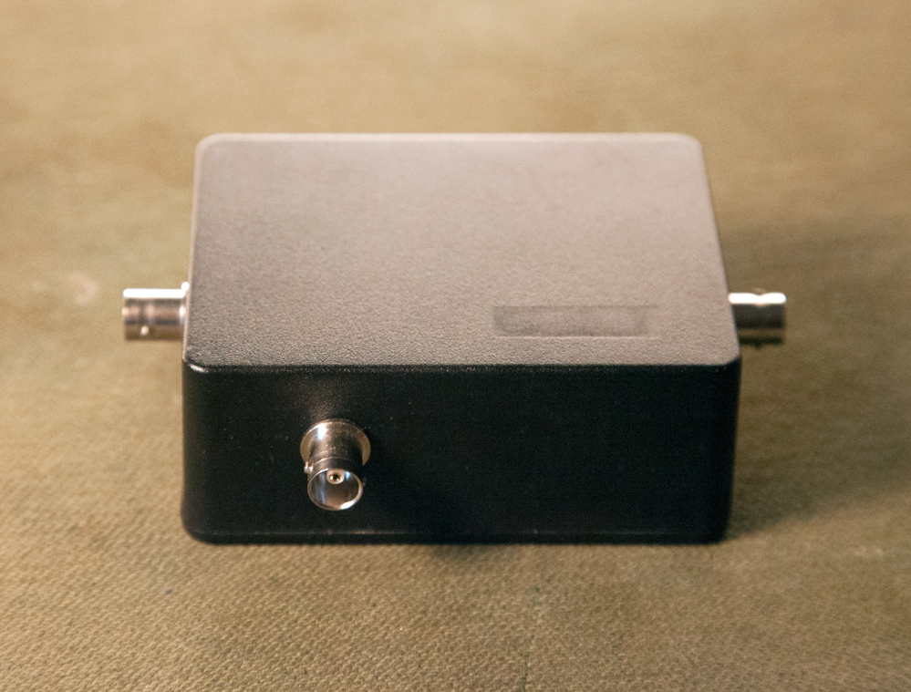
Anyway, since it’s a common problem, a simple – cheap – and easy solution would be in order. As a first attempt, this CVBS Demangler would like to fit the bill. (okay, full disclosure, i’ve been trying a number of approaches, but this has been the first to come close enough to the mark to bother mentioning at this point)
So I’ve built one of these things now, and so far so good. I’ve been using it as kind of an output module for video experimentation for a while now, and i’ve performed a few tests with good results.
(okay, actually, it’s been giving awesome results…but more testing of it’s limits are in order i think)
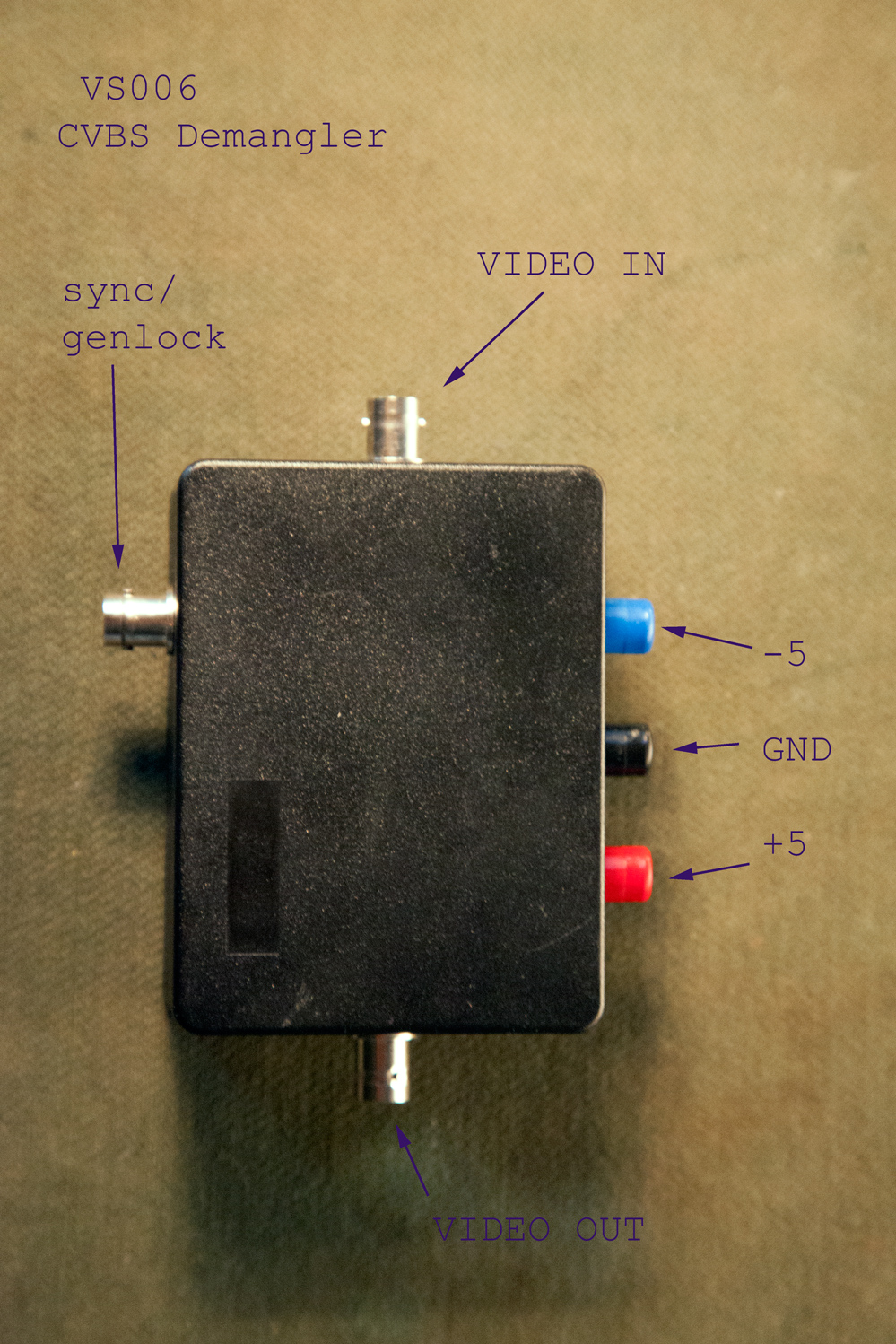
What it does:
-you run a clean video source into the Demangler’s “sync/genlock” input,
-and run your corrupted video into the main video input,
-the composite sync from the “sync/genlock” video input is added to (or really subtracted to) the other, main video input,
-and voila: a recordable, projectable video signal.
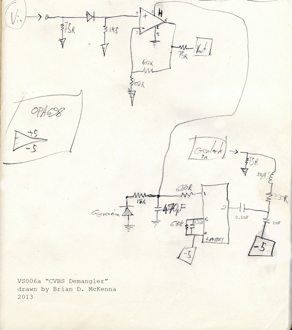
How it works:
The circuit uses a sync-separator (the ubiquious LM1881), and a voltage-limiting-opamp (OPA698). The opamp buffers the video input and drives the video output – it also clips the video signal down to an acceptable voltage and removes any unwanted excursions of signal into the video output’s sync area.
See, the sync/genlock input is lowpass filtered with the little 33uH inductor, 33ohm resistor, and 1 nanoFarad capacitor – and then fed into the LM1881’s video input at pin2. Note the 75ohm terminating resistor and 0.1 microFarad decoupling capacitor also. The LM1881’s composite-sync output (@pin1) is used to control the ‘high’ voltage limit of the OPA698. So in this case, when the LM1881 sends a sync pulse, the OPA698 output is held low for the duration of the pulse. A germanium diode helps keep the voltages in check, and the 470pF cap also helps in the smoothing out of some spikes.
When no sync is present, the 1881’s composite-sync output is floats at 2 volts. This makes the OPA698 clip off anything over 2 volts from its video output signal. The 402ohm resistors set the opamp’s gain at 2, so after driving a normal 75ohm load, you should end up with something more or less where it needs to be.
The setup will work with NTSC and PAL.
What it doesn’t do:
There’s no DC restoration on this thing.
Here’s the inside:
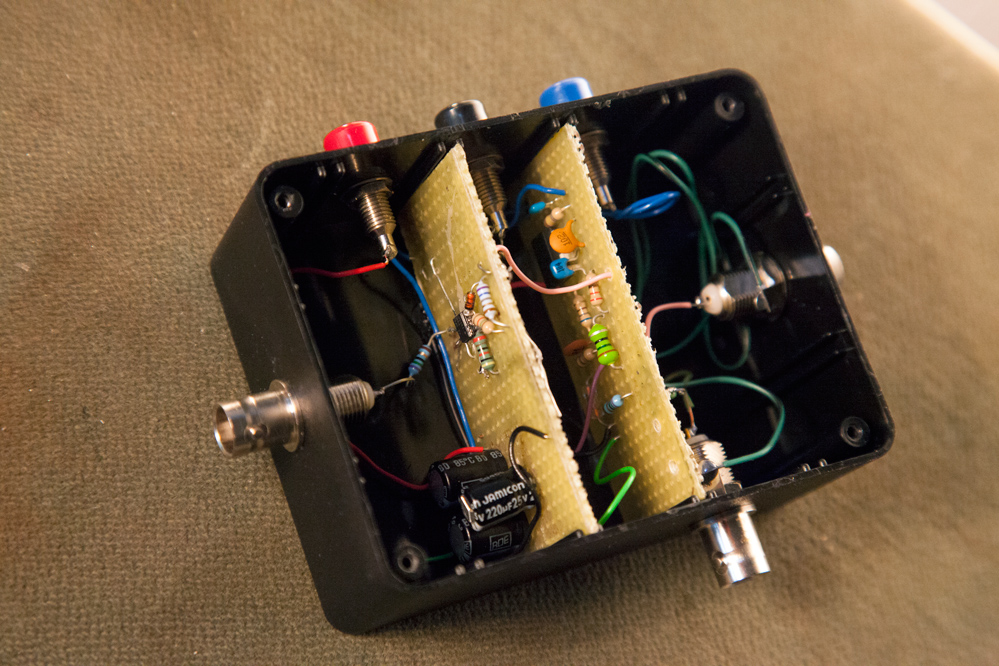
Note the OPA698, it only comes in surface mount packages, so it’s glued onto the perf-board with some wires soldered onto the pins.
Component layout, wire length, wire thickness and all that can become really important in highspeed applications, but no problems have been experience with this thing.
The 3 big (220uF) power supply decoupling capacitors in there are wired like this:
[+5] —-|(—- GND
GND —–|(—- [-5]
[+5] —-|(—- [-5]
(if that makes any sense)
Here’s the rest of the schematic:
One notable limitation:
The way in which I use this thing, is to split the video source I want to manipulate with a (BNC) T-connector, sending one line to my video experiment, and one line to the Demangler sync input. Such an approach will probably fail with really freaky video feedback experiments. Best would be to use 2 independent outputs from the video source if available. For future versions I’d like to include an extra video buffer. This would be to insure that the sync input from the video source remains unmolested in a wider variety of patching schemes and wacky experiments.
Okay, so if anyone happens to get one of these working, or if anyone has any questions, give me shout.
oh,
and some similar things which do similar things but with different approaches can be found here:
the Synkie sk02-resyncer: http://synkie.net/modules/sk02-resyncer/
Karl’s Sync Corrector: http://www.karlklomp.nl/mda/other.html
Gijs’s Timebase Forcer: http://gieskes.nl/visual-equipment/?file=time-base-forcer


http://www.recordingmedium.com/video/dnk-b-synth-excerpt-sm.mov
2:23min, 480×640, 15fps, H.264, 18.8MB
shot nov 1st, 2010 at SMART-Project-Space, Amsterdam by Mike Ottink
from Call & Response Festival.
i played a live set for video-projector and 8.1 sound-system
this cut is from the very start:
http://vimeo.com/16731102
filmed on a phone by Vasco (thnx)


okay maybe that’s half true.
‘blogging’ at any rate started to suck, mainly because of spam and catastrophic sever hacks/crashes. comments might be possible, but registration? not sure at this point.
but anyway, in the meantime i managed to put a few of these things together:
 …not a ‘circuit-bent’ commodore… i threw out the mother-board and built a new circuit which makes use of the keyboard’s inherent touch-sensitivity. this thing outputs 800×600 VGA signals, consequent audio, and provides for the mixing and manipulation of whatever else you plug into it.
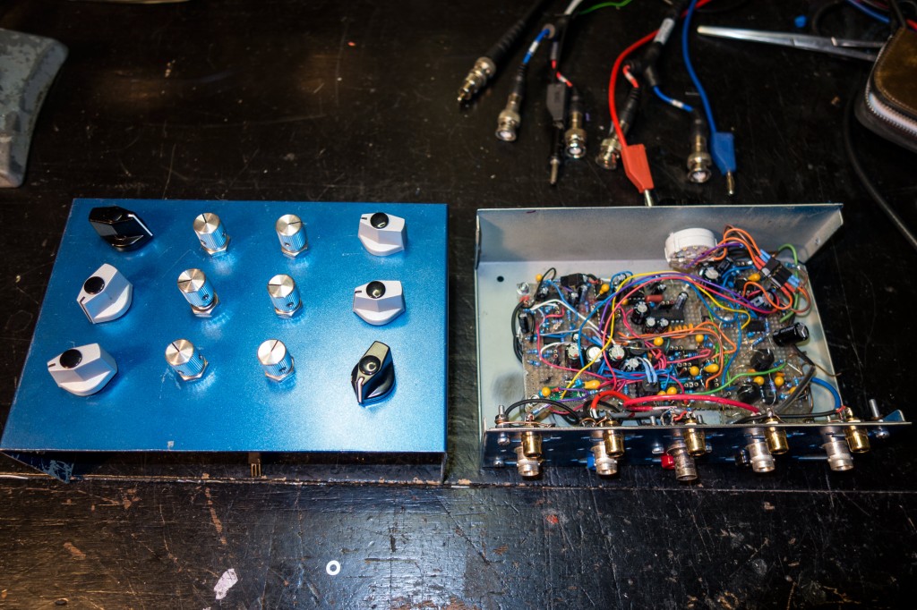
this machine dubbed afterbirth, is a performance instrument for some ongoing projects. it’s older brother called the long slow death of nostalgia (for some reason) got one performance before its induction into the museum system.
here’s my first assembly language project in the works:

i started with the program from here: “http://yusoft.kulichki.com/english/pic/my_proj.htm”:http://yusoft.kulichki.com/english/pic/my_proj.htm
it didn’t work until i added the 555 part of “this circuit”:http://yusoft.kulichki.com/english/pic/my_proj.htm in order to get the V-synch pulse-width right.
this spurred a rewrite of the program. this synched without the extra PWM stuff…
i added an extra output to function as a gate to control a 4066 switch for proper RGB blanking.
everything worked fine in the middle of the screen,
but the top of the image was skewed:
rather than try to fix this,
i moved on to making an SVGA 800×600 @ 60Hz program based on the timing info found here: “http://tinyvga.com/vga-timing/800×600@60Hz”:http://tinyvga.com/vga-timing/800×600@60Hz (and some other details elsewhere)
this runs on a 20MHz crystal which, if you do the math = exactly 100 instructions / visible line and nice round numbers for all the sync and blanking periods.
for fun i followed up with a 1024×768 @ 60Hz version:

happily this program actually worked first try, however, the skewed image thing returned.
with a lot of tuning to the Vsync areas i minimized the skew to just a small bump at the top, but i’m not sure how portable this thing would be with less forgiving monitors.
for this version i also added 75ohm terminating resisters to the RGB outputs.
i’m thinking that the ratios between vertical and horizontal sync times have a lot to do with the skewing thing. so far, this last version looks just the same whether the the processor clock is running at 18, 20, or 17.7344 MHz.
the 800×600 version has at least all the correct ratios. so next step is to use this as the core of a new AV synth.